
Project 05Pressure equipment
Pressure vessel weldment
A 316L vessel with a clamp closure at the base and a weldment drawing specific enough for a coded shop to build it.
- Body
- 8″ Sch40S · 316L
- Overall
- 700 mm · Ø203.2
- Closure
- 4″ ferrule + clamp
- Weld prep
- 35° bevel
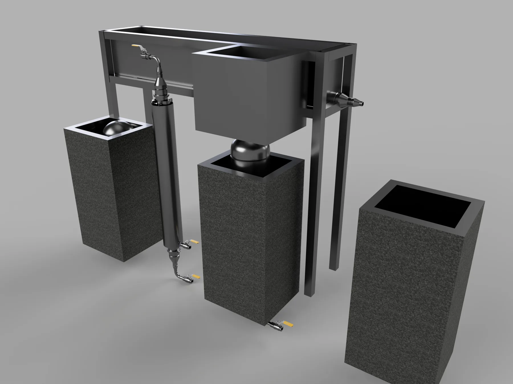
A 316L vessel that forms part of a client’s assembly. It has to hold pressure and still open for service, so the base closes on a 4″ ferrule and high-pressure clamp rather than a welded cap. A non-disclosure agreement was signed for this project: the weldment is shown, the client and application are not.
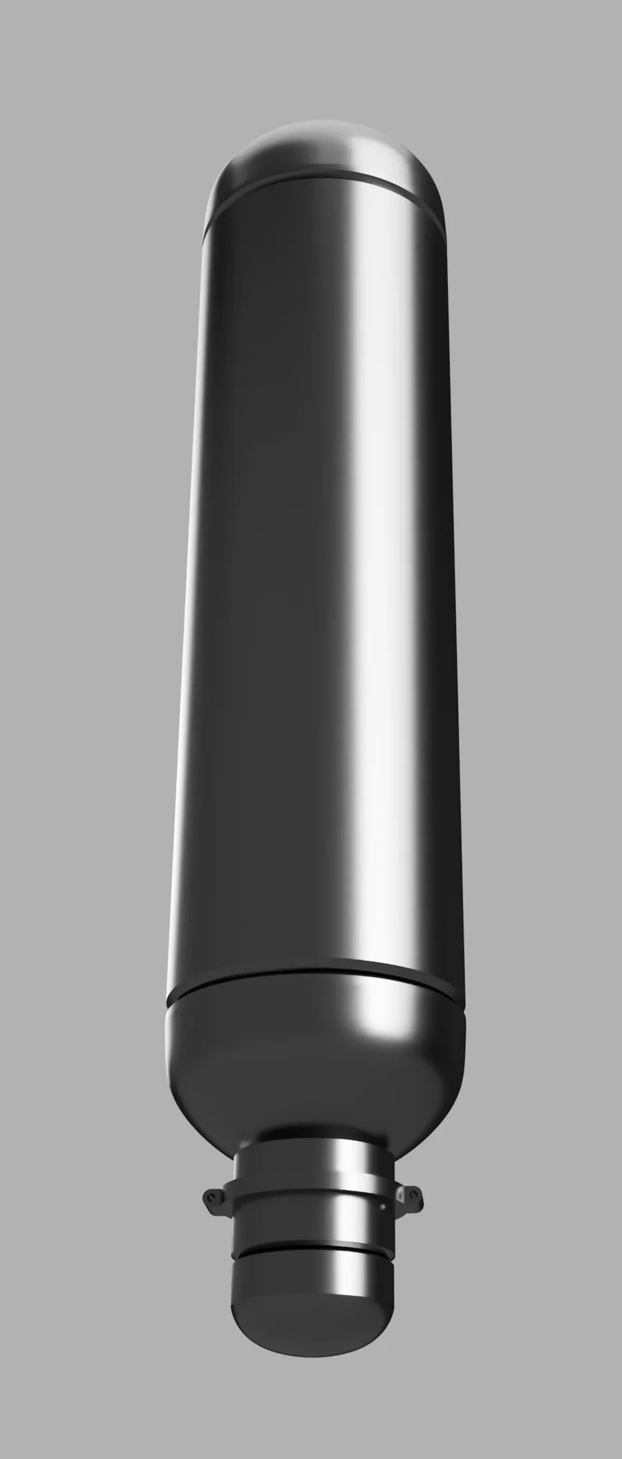
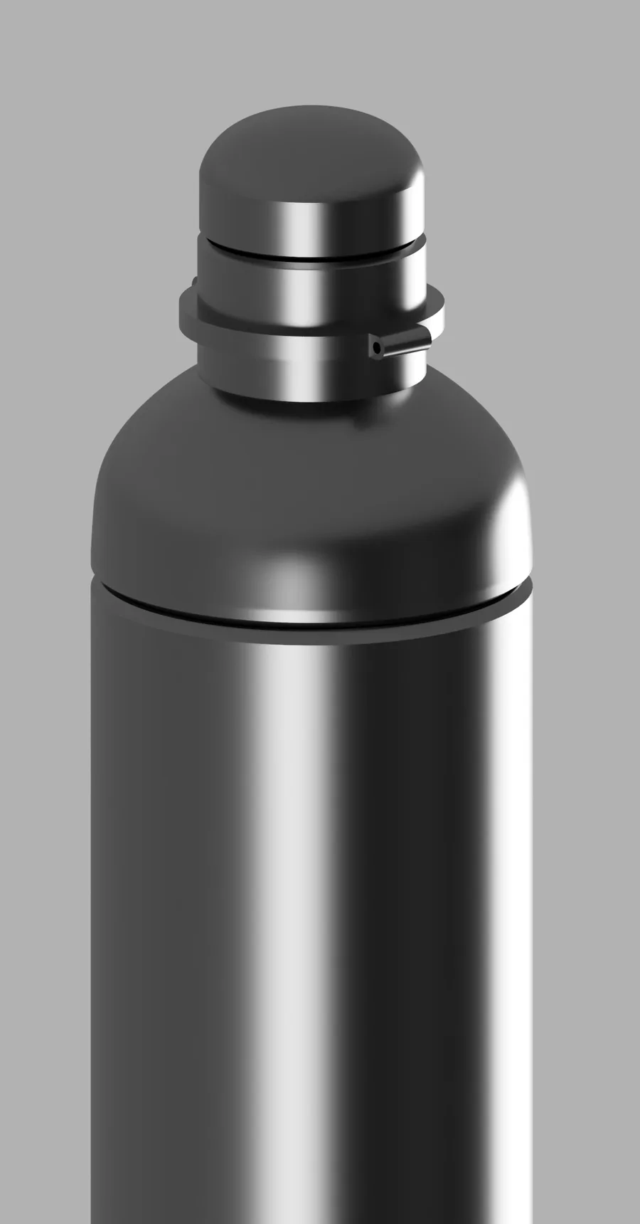
The base is the interface. A 4″ ferrule welded to the body takes a high-pressure clamp, which is how the vessel couples to the client’s assembly and why it can be taken off again. Everything above it is closed by an 8″ weld cap, so in service the only way in is at the bottom.
The problem
Welded shut, a vessel holds pressure but cannot be opened. A clamp closure can, but only if the ferrule behind it is welded as a pressure boundary. The drawing had to specify that joint well enough for a shop to repeat it: bevel, gap, purge and filler are not workshop preferences.
What I designed
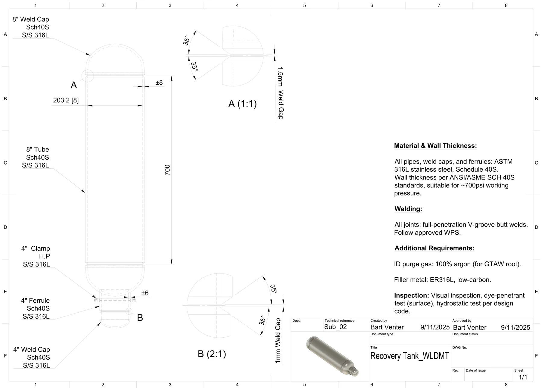
Schedule 40S pipe and weld caps for the body, with a ferrule welded to the base and the clamp and 4″ cap closing it. Joints are full-penetration V-groove at 35°, root gaps dimensioned at 1.5 mm and 1 mm, GTAW root with a 100% argon purge and ER316L filler. Inspection is visual, dye-penetrant and hydrostatic.
Drawings
The weldment sheet: main elevation, two enlarged joint details, and the fabrication notes that govern how it is made and inspected.
Details that mattered
Weld preparation
35° bevel each side, full penetration, with the root gap dimensioned in detail views at 1:1 and 2:1.
Purge and filler
Argon behind the root, ER316L low-carbon filler. Without the purge the root oxidises and the weld is not what the design assumed, however it looks from outside.
Inspection
Visual, dye-penetrant and hydrostatic, in that order, so the vessel can be released.
Tolerance
±6 mm on principal dimensions, 203.2 mm body diameter. Tolerances set where fit-up needs them rather than applied uniformly.
What it gives the client
What the client gets is a weldment drawing a coded shop can pick up: material, joint geometry, purge, filler, tolerances and inspection, with the closure designed so the vessel is serviced rather than cut open. Work like this suits stainless fabricators and equipment builders specifying a pressure boundary.
Delivered under a non-disclosure agreement. The drawing specifies code-grade practice; certification and pressure rating belong to the fabricator holding the relevant stamp and the authorised inspection route, and are not claimed here. The note block states a working pressure of approximately 700 psi for this section.