Project 04Process plant
Essential oil separator
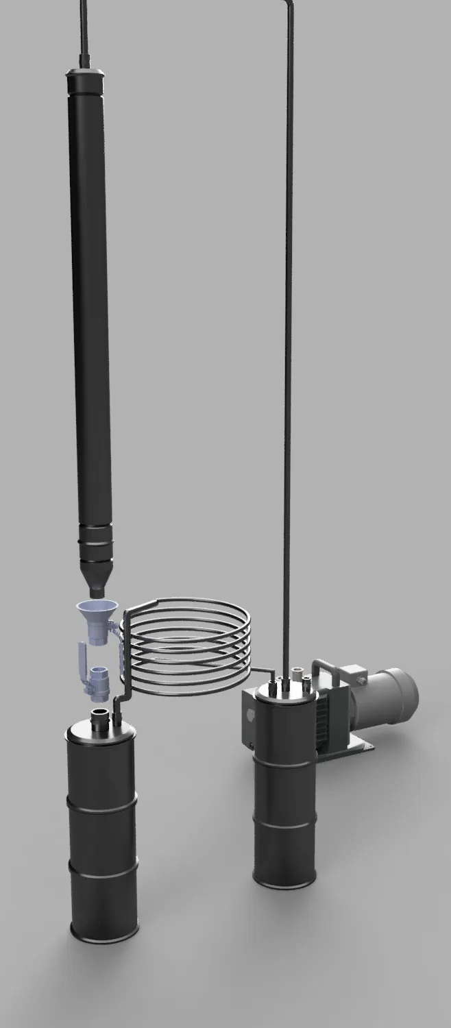
A vacuum separator with four columns that can be swapped while the process runs, and a cold trap that protects the pump.
- Columns
- 4 × 2.5″ Sch40S
- Cold trap
- Ø300 mm, 6 turns
- Receivers
- 2.8 L + 7.8 L
- Vapour line
- 3/8″ SS316
A separator for a client already running the process continuously. The constraint was not the separation but the stopping: changing a column meant stopping production with it.
The problem
Continuous operation and maintenance pull in opposite directions. The process wants nothing interrupted; the plant needs a column changed. And the product is heat-sensitive, so the separation has to run at the lowest temperature that will do the job. Under vacuum, whatever does not condense goes into the pump — and the light fraction is both the most valuable and the least likely to condense.
What I designed
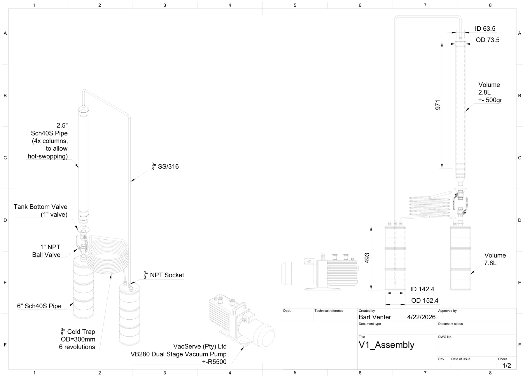
Four 2.5″ Sch40S columns in parallel, each isolatable at the bottom valve, so a change is a swap rather than a shutdown. Vapour leaves through 3/8″ SS316 to a cold trap wound at 300 mm diameter over six turns, then to the pump. Condensate collects in 2.8 L and 7.8 L receivers.
Four columns, not one larger one
Capacity is matched by running more columns, and a change happens without stopping the process.
Isolation at the column
Each column closes off without breaking vacuum on the others. That is what makes the hot-swap practical.
Trap sized for the light end
The largest cold surface in the system sits where the escaping fraction is caught, protecting the pump and recovering the part worth recovering.
Details that mattered
Pressure as the mechanism
Lower pressure lowers the boiling point. That is what lets the separation run at a temperature the terpenes survive.
Trap versus condenser
The condenser takes the bulk; the trap takes what passes it, so it has to be colder by a working margin.
Fouling
In continuous duty the condensing surface is where throughput is lost. Viscous condensate builds before anything visibly fails.
Receiver volumes
7.8 L matches 142.4 mm ID over 493 mm, and 2.8 L matches the 63.5 mm bore over the drawn length, less fittings. The volumes are consistent with the pipe sizes.
What it gives the client
The rig is shaped around the client’s operating pattern: four columns, isolation at each, and a trap that holds on to the fraction that would otherwise be lost. Work like this suits extraction equipment builders and producers running continuous thermal processes.
No yield, purity or throughput figure is claimed: the supplied material documents the design and the process arrangement, not measured results.
Drawings
One labelled assembly sheet defining the columns, trap, receivers and pump, with the working volumes and pipe sizes.