Project 02Process refrigeration
Custom freeze dryer assembly
A freeze dryer built into a client’s existing machine, running one refrigeration circuit and serving a second function in their design.
- Refrigeration
- Single-stage
- Cold trap
- Refrigerated pot
- Chamber lid
- 250 × 250 × 15 mm
- Heat input
- Warm water bath
The client needed a freeze dryer built into an existing machine rather than supplied as a separate unit, and it had to serve a second function inside their design. That pointed away from a specialist circuit and towards parts they already had. A non-disclosure agreement was signed for this project: the design is shown, the client and application are not.
The module is self-contained: chamber, cold trap, refrigeration circuit and pump are built as one assembly that connects to the host machine rather than being threaded through it. That is also what makes the second duty practical, because the refrigeration side is shared instead of duplicated.
The problem
Freeze drying needs heat and cold in the same enclosure: too little heat and sublimation stalls, too much and the product thaws. Whatever leaves the product also has to be caught before it reaches the pump. The harder constraint was fitting a second job into the same circuit without making it something only a specialist could repair.
What I designed
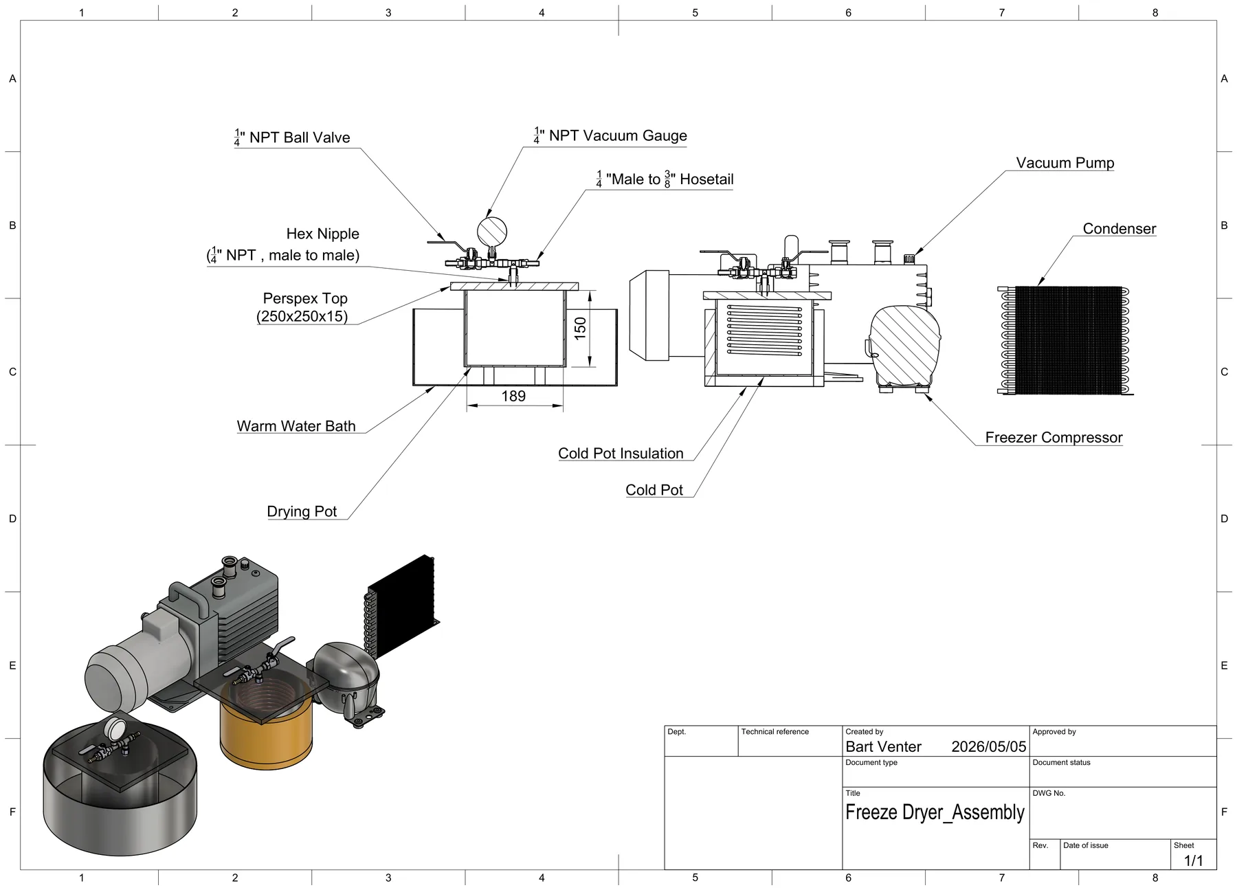
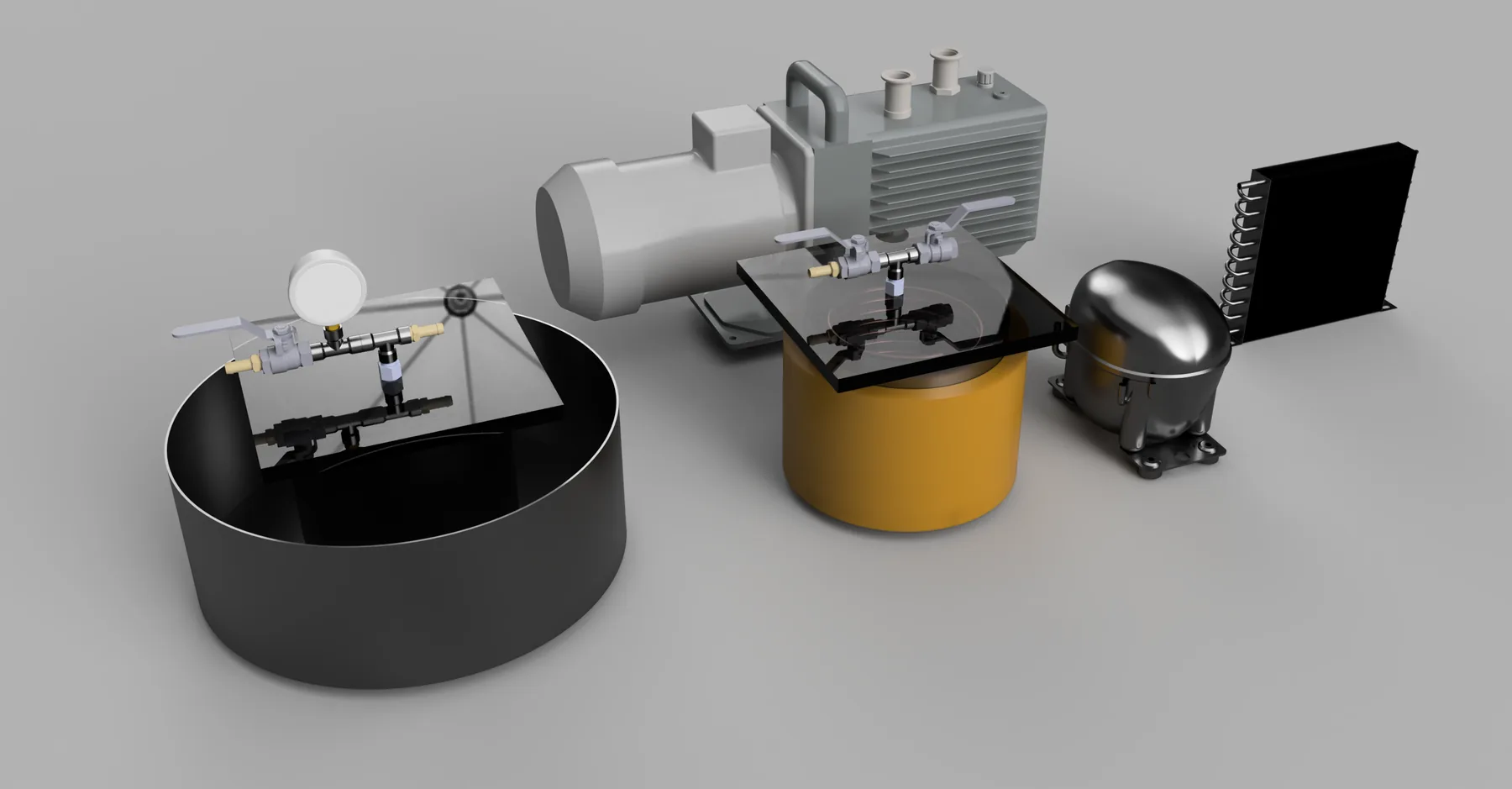
One vapour-compression circuit, a standard freezer compressor and a finned condenser cooling an insulated pot. A warm water bath heats the drying pot through its wall, the Perspex lid seals the chamber, and a 1/4″ NPT manifold on the lid carries the gauge, isolation valve and hose tail. Vapour runs chamber, trap, pump.
One circuit, not a cascade
A single stage can be repaired with ordinary refrigeration parts and shares components with the rest of the client’s machine.
Trap upstream of the pump
Water condenses on the cold pot instead of being pulled through the pump.
A bath instead of a controller
The water holds its temperature by thermal mass, so the heat input does not depend on a control loop.
Details that mattered
Chamber pressure
Primary drying runs in the 50–200 mTorr band. The gauge is there because pressure is the process variable.
Trap temperature
Colder than the vapour it is catching, with margin. The insulation is what keeps compressor capacity in the trap rather than the room.
Path restriction
Every fitting between chamber and trap adds resistance. The manifold is short and the bore sized to the pump.
What it gives the client
The drawing defines the vapour path, the sealing arrangement and the instrumentation as one assembly that drops into an existing machine. Work like this suits equipment builders adding a duty to a machine they already have, and plant operators who do not want a second standalone unit.
Delivered under a non-disclosure agreement. No drying performance, throughput or product-quality result is claimed: the supplied material documents the design, not test data.
Drawings
One assembly sheet, with the vapour path labelled end to end.